Everything You Need to Know About Bracing Portal Frames
Portal Frames charts and details provide a quick reference for architects to use when it is not possible to obtain the required bracing demand

Portal frames are an effective way to achieve bracing
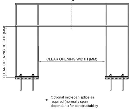
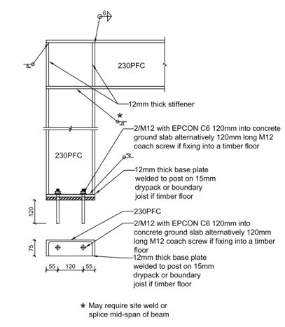
When there are minimal lengths of walls on the bracing lines or one is unable to obtain the required bracing demand for the bracing lines. These are often constructed using steel parallel flange channels (PFCs) as PFCs are readily accommodated within the wall framing.
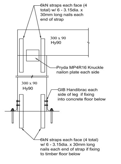
Portal frames can also be constructed using timber as well. However, timber portal frames have limited application and are unlikely to provide the necessary bracing units for many applications due to low stiffness in comparison to steel.
Quick reference charts for architects and builders
The charts and details below provide a quick reference for architects to use when it is not possible to obtain the required bracing demand.
Portal frame design requires engineering sign-off for Council submission as it is Specific Engineering Design (SED) and outside the scope of NZS 3604. Typical details have been provided for a 230PFC portal frame and 300 x 90 Hy90 timber portal frame. If you require further assistance with bracing or sign-off on a portal design in your building, please get in contact with ProConsult. We can offer efficient design solutions for your bracing requirements.
It is important to note the limitations below and the sizes indicated are the minimum required sizes for the spans and very light loads.

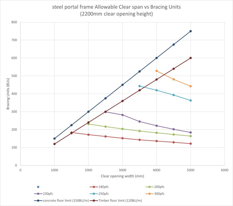
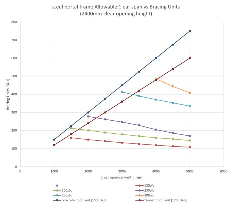
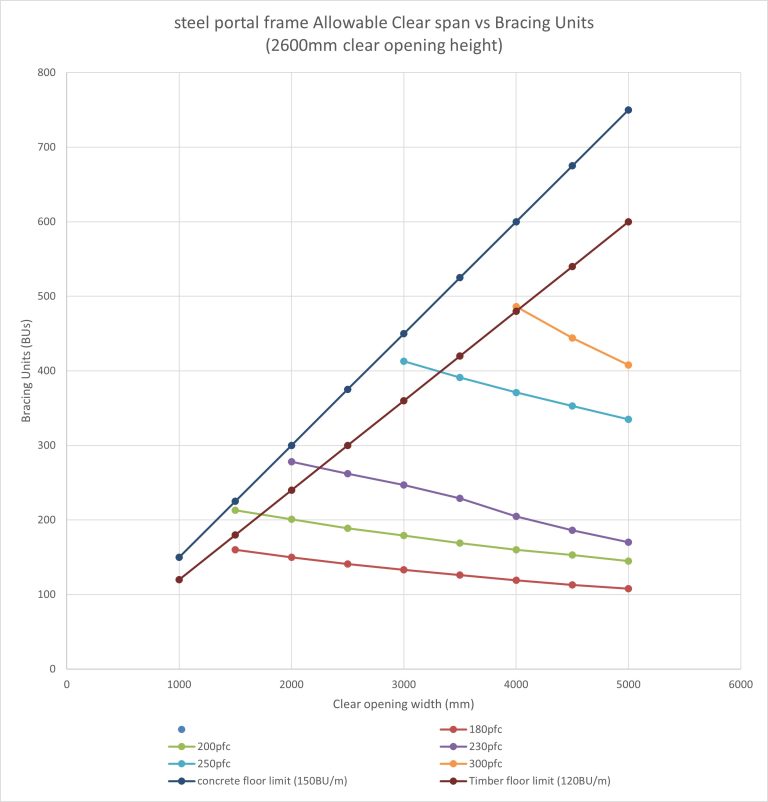
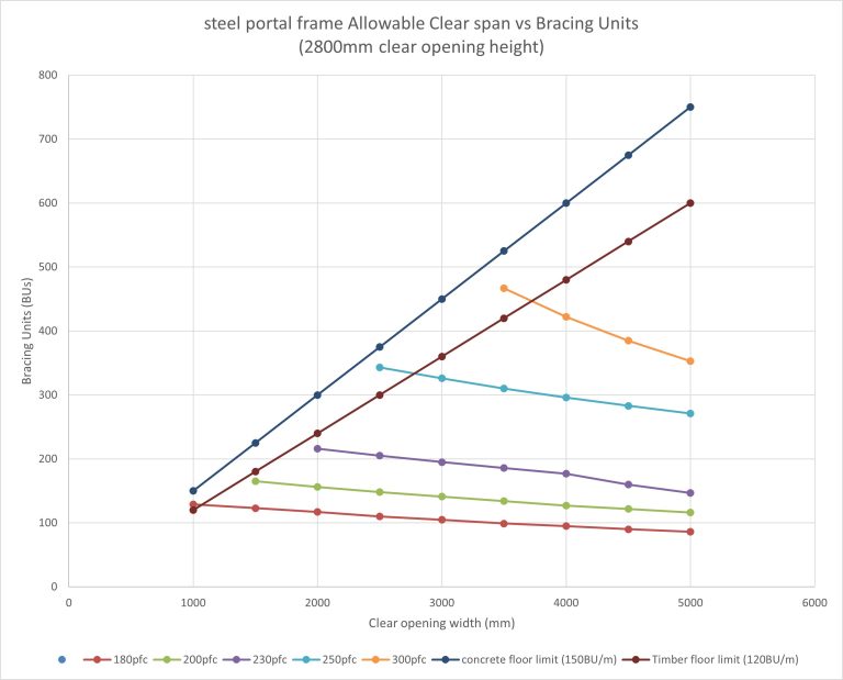
How to use the charts below for Engineering Certification
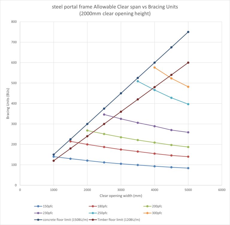
- Number of bracing units you require your portal to withstand.
- Type of floor system in the building (timber or concrete).
- Ensure the selected size of portal frame provides a clear opening distance which is above the timber floor limit line or concrete floor limit depending on type of floor. If your selection is below the concrete floor limit of 150BUs/m the foundation will also need to be specifically designed to provide the bracing demand required.
Limitations to the charts below for Engineering Certification
- The spans given assume no vertical load on the portal frames and are an initial selection guide only – they can be used for upper floors in the gable ends with light roofs.
- Each portal frame will need to be specifically designed by a Chartered Professional Engineer (CPEng) to accommodate load versus span.
- The portal frames have been designed to an 8mm SLS deflection limit (Serviceability Limit State) as per the requirements of the BRANZ Technical paper – P21 (2010) – A wall bracing test and evaluation procedure and adjusted for ULS µ factor 1.25 in accordance with current good practice.
Steel portal frame allowable clear span vs bracing units charts
How to get Council Engineering Certification for your Portal Frame plans
ProConsult have been engaged with many portal frame designs through the country. Please contact us today to discuss your requirements.

Author: Stewart Hobbs - Principal Engineer at ProConsult
Stewart is the journal editor for SESOC (Structural Engineering Society New Zealand (Inc.)
what our clients have to say


